
Real-Time Ray-Tracing [1]: Vulkan Pipeline
- Ray-Tracing pipeline in Vulkan
- Ray-Tracing reflection and refraction
- Different geometry types in acceleration structure
- Heightmap based water simulation and caustics rendering
- Other features in Ray-Tracing Pipeline
- Vulkan synchronization: Fence, Femaphore and Pipeline-barriers
- Miscellaneous
- References
Ray tracing and rasterization are two common solutions in real-time rendering. Rasterization, with its natural suitability for parallel acceleration (like good data locality), was what the earliest GPUs were designed for. In recent years, companies like NVIDIA, AMD, and Intel have introduced hardware units specifically designed to accelerate ray tracing, making hardware-accelerated ray tracing increasingly feasible. Even on mobile devices, many high-end chips are now offering dedicated hardware support for ray tracing, such as Ray Query and the Ray-Tracing Pipeline. These technologies are expected to become more widespread in the near future (this article was written in November 2024).
To dive deeper into the Vulkan Ray-Tracing Pipeline, I implemented a scene on the open-source framework Vulkan-Samples that showcases effects such as ray-traced reflections, refractions, water surface height field simulations, caustics generation, and rendering. In the implementation, the water surface height field simulation was done using the Vulkan Compute Pipeline, while caustics generation utilized the Graphics Pipeline, and the final rendering effect was achieved through the Ray-Tracing Pipeline. This process involved the organization and synchronization of rendering resources, the construction of acceleration structures within the Ray-Tracing Pipeline, and the application of various shader types.
This article mainly serves as a personal learning note, so there may be some shortcomings or inaccuracies. I welcome any feedback or corrections from readers.
Ray-Tracing pipeline in Vulkan
Based on Kajiya’s rendering equation, ray tracing is a technique where multiple rays are cast from the camera position as the origin, passing through each pixel in the rendered image. These rays travel through the scene with a certain probability, simulating the reflection, refraction, absorption, and surface shading of light as it interacts with the scene. The final pixel color is computed through this process (detailed further through Monte Carlo integration).
To accelerate the convergence of Monte Carlo integration, efficient sampling and denoising methods are crucial for speeding up the ray tracing process. For more detailed information on ray tracing, you can refer to the following links: Ray Tracing in One Weekend and Monte Carlo Integration.
Vulkan is a high-performance, cross-platform graphics and compute API maintained by the Khronos Group. To support ray tracing, Khronos introduced a series of extensions in Vulkan:
- VK_KHR_ray_tracing_pipeline: Allows developers to use dedicated shaders, such as Ray Generation, Intersection, and Closest Hit shaders, to implement ray tracing effects.
- VK_KHR_acceleration_structure: Provides functionality for managing acceleration structures, such as creating and updating BVH (Bounding Volume Hierarchy).
- VK_KHR_ray_query: Enables ray query functionality in any shader stage without needing to build a complete ray tracing pipeline, commonly used for shadow and ambient occlusion (AO) rendering.
- Extensions like VK_KHR_deferred_host_operations and VK_KHR_pipeline_library: Optimize the construction of acceleration structures and improve the loading performance of ray tracing pipelines.
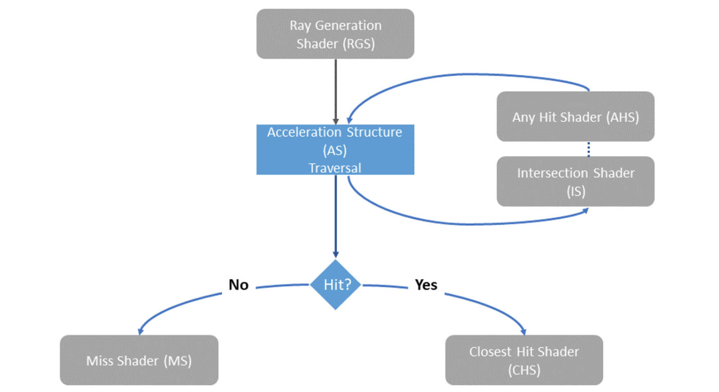
The diagram below illustrates the flow of the Vulkan Ray-Tracing Pipeline. For each pixel, the Ray Generation Shader is executed, casting rays towards pre-built acceleration structures. The Intersection Shader then checks whether the ray intersects with any objects in the scene and retrieves intersection information. If an intersection is found, the corresponding Hit Shader is executed; otherwise, the Miss Shader is run.
The Hit Shader consists of the Closest Hit Shader and the Any Hit Shader: the former processes the closest intersection to the origin after ray tracing, while the latter is executed at each hit point and is commonly used for rendering effects like transparency.
vkCmdTraceRaysKHR is the Vulkan command for executing ray tracing, similar to vkCmdDispatch and vkCmdDrawIndexed, but for initiating ray tracing computations. Its main parameters are as follows:
void vkCmdTraceRaysKHR(
    VkCommandBuffer commandBuffer,
    const VkStridedDeviceAddressRegionKHR* pRaygenShaderBindingTable,
    const VkStridedDeviceAddressRegionKHR* pMissShaderBindingTable,
    const VkStridedDeviceAddressRegionKHR* pHitShaderBindingTable,
    const VkStridedDeviceAddressRegionKHR* pCallableShaderBindingTable,
    uint32_t width,
    uint32_t height,
    uint32_t depth
);
In ray tracing, the Shader Binding Table (SBT) plays a crucial role. It binds one or more shaders to their resources and allows the GPU to efficiently switch and execute different shaders during the ray tracing process. The use of SBT greatly enhances the flexibility and performance of ray tracing, enabling dynamic shader invocation and resource binding as rays traverse through the scene. This mechanism is key for implementing complex effects such as reflections, refractions, and shadowing in a performant manner.
Additionally, Vulkan introduces the concept of Shader Group, which organizes specific shaders through the VkRayTracingShaderGroupCreateInfoKHR structure. For example, the closestHitShader can have several types. If the type is VK_RAY_TRACING_SHADER_GROUP_TYPE_TRIANGLES_HIT_GROUP_KHR, it indicates that the shader performs ray-triangle intersection calculations on geometry data, retrieving intersection information. On the other hand, if the closestHitShader uses the VK_RAY_TRACING_SHADER_GROUP_TYPE_PROCEDURAL_HIT_GROUP_KHR type, it means that the geometry is not a triangle mesh but rather a user-defined shape. In this case, an appropriate intersectionShader must be provided to handle the ray-geometry intersection calculations.
Ray-Tracing reflection and refraction
In this scene, only specular reflections are considered, with a single reflection ray and a single refraction path. In contrast, diffuse reflection and scattering are more complex, involving intricate sampling and denoising algorithms (which are critical issues in real-time ray tracing renderers). Since the focus of this scene is on learning the usage of the Vulkan Ray-Tracing Pipeline, the handling of diffuse reflection and scattering will not be discussed here and will be explored further in future studies.
The laws of reflection and refraction are well-known physical principles, and their mathematical expressions are relatively simple. The reflection and refraction of rays are essentially recursive processes. However, excessive recursion can lead to performance bottlenecks, impacting the efficiency of ray tracing. Referring to the implementation in the Vulkan Sample Ray-Tracing Reflection Case, we can set the maximum depth for reflections/refractions iteratively. This approach is more suitable for SIMD architectures, as it promotes uniform thread execution. Additionally, this explicit loop structure is easier for compilers to optimize, such as through register optimizations to reduce memory access frequency.
// Reflection
vec4 origin = init_origin;
vec4 direction = init_direction;
vec3 color = vec3(1.0);
for (int i = 0; i < MAX_RECURSION; i++)
{
  traceRayEXT(topLevelAS, gl_RayFlagsNoneEXT, 0xff, 0, 0, 0, origin.xyz, tmin, direction.xyz, tmax, 0);
  vec3 hitColor = rayPayload.color;

  if (rayPayload.distance < 0.0f)
  {
    color *= hitColor + 0.0001 * absortion;
    break;
  } else if (rayPayload.reflector > 0.5f)
  {
    color = mix(color, hitColor, absortion);
    const vec4 hitPos = origin + direction * rayPayload.distance;
    // Do reflection and update ray origin and direction
    origin.xyz = hitPos.xyz + rayPayload.normal * 0.001f;
    direction.xyz = reflect(direction.xyz, rayPayload.normal);
  } else if (rayPayload.refractor > 0.0f)
  {
    color = mix(color, hitColor, absortion);
    const vec4 hitPos = origin + direction * rayPayload.distance;
    vec3 refractNormal;
    // Calculate refraction for double-sided surface
    if (rayPayload.refractor < 1.0f)
    {
      refractNormal = rayPayload.normal;
    }
    else
    {
      refractNormal = -rayPayload.normal;
    }
    // Do refraction and update ray origin and direction
    origin.xyz = hitPos.xyz - refractNormal * 0.001f;
    direction.xyz = refract(direction.xyz, refractNormal, rayPayload.refractor);

  } else
  {
    color *= hitColor + 0.0001*absortion;
    break;
  }
}
hitValues += color;
Different geometry types in acceleration structure
In ray tracing algorithms, the process of calculating ray-geometry intersections is highly time-consuming, so acceleration structures are needed to alleviate this. In hardware-accelerated ray tracing, the main form of acceleration comes from these structures. The Vulkan API provides a structure related to acceleration structures, as shown in the following code snippet:
typedef struct VkAccelerationStructureInstanceKHR {
    VkTransformMatrixKHR          transform;
    uint32_t                      instanceCustomIndex:24;
    uint32_t                      mask:8;
    uint32_t                      instanceShaderBindingTableRecordOffset:24;
    VkGeometryInstanceFlagsKHR    flags:8;
    uint64_t                      accelerationStructureReference;
} VkAccelerationStructureInstanceKHR;

As seen in the diagram, the Top Level Acceleration Structure (TLAS) contains multiple instances, with each instance corresponding to one or more Bottom Level Acceleration Structures (BLAS). From the diagram, we can observe that different instances can be connected to the same BLAS, while each instance can have its own unique transformation matrix, allowing the same geometry to be placed at different locations in the scene.
Furthermore, BLAS allows for custom geometries. For example, a sphere can be defined using a mathematical formula, but the AABB (Axis-Aligned Bounding Box) for the BLAS must be explicitly provided. This AABB is crucial for accelerating intersection tests during ray tracing.
When different BLAS require different shaders (e.g., a BLAS made of triangles versus a BLAS made of procedural geometry), you can bind different shaders by setting the instanceShaderBindingTableRecordOffset. This offset points to the appropriate record in the Shader Binding Table (SBT), ensuring that the correct closestHitShader and intersectionShader are used for each BLAS.
The instanceCustomIndex can serve as a unique identifier for each BLAS and can be passed to shaders, allowing you to efficiently execute operations for different geometries on the GPU.
For example, sphere-related intersection logic can be implemented as follows:
struct Sphere {
	vec3 center;
	float radius;
};

// Ray-sphere intersection
// By Inigo Quilez, from https://iquilezles.org/articles/spherefunctions/
float sphIntersect(const Sphere s, vec3 ro, vec3 rd)
{
    vec3 oc = s.center - ro;
    float b = dot(oc, rd);
    float c = dot(oc, oc) - s.radius * s.radius;
    float h = b * b - c;
    if (h < 0.0) {
        return -1.0;
    }
    h = sqrt(h);
    return b - h;
}
The intersection logic for a rectangle composed of two triangles is as follows.
struct Plane
{
	vec4 center;
	vec4 normal;
	vec4 points[4];
};

/*
// o: origin, 3-dimension
// d: direction, 3-dimension
// h: distance, scalar
// n: plane normal
// line: o + h * d
// Intersection point of a line and a plane:
// dot(o + h * d - c, n) = 0
// h = dot(c - o, n) / dot(d, n)
// Then check if intersection point is in the rectangle.
*/
float planeIntersect(const Plane p, vec3 ro, vec3 rd)
{
    float h = dot(p.center.xyz - ro, p.normal.xyz) / dot(rd, p.normal.xyz);
    vec3 hPoint = ro + h * rd;

    bool valid = false;
    // Test first triangle
    {
        vec3 v1 = p.points[0].xyz/p.points[0].w - hPoint;
        vec3 v2 = p.points[1].xyz/p.points[1].w - hPoint;
        vec3 v3 = p.points[2].xyz/p.points[2].w - hPoint;
        if (length(v1) == 0 || length(v2) ==0 || length(v3) == 0)
        {
            valid = true;
        }
        else
        {
            vec3 v4 = cross(v1, v2);
            vec3 v5 = cross(v2, v3);
            vec3 v6 = cross(v3, v1);

            float v7 = dot(v4, v5);
            float v8 = dot(v5, v6);

            bool inside = v7 >= 0.0 && v8 >= 0.0;
            valid = valid || inside;
        }
    }

    // Test second triangle
    {
        vec3 v1 = p.points[2].xyz/p.points[2].w - hPoint;
        vec3 v2 = p.points[3].xyz/p.points[3].w - hPoint;
        vec3 v3 = p.points[0].xyz/p.points[0].w - hPoint;
        vec3 v4 = cross(v1, v2);
        vec3 v5 = cross(v2, v3);
        vec3 v6 = cross(v3, v1);

        float v7 = dot(v4, v5);
        float v8 = dot(v5, v6);

        bool inside = v7 >= 0.0 && v8 >= 0.0;
        valid = valid || inside;
    }

    if (!valid)
        return -1.0;

    return h;
}
Heightmap based water simulation and caustics rendering
To enhance interactivity, we added a heightfield-based water surface simulation and Caustics rendering to the scene, with mouse interaction implemented. The algorithms for the heightfield and Caustics rendering are based on Evan Wallace’s WebGL Water implementation. The water surface is represented by a high-resolution heightfield image, which contains four channels: relative height, the speed of sea surface height changes, and the normalized x and z components of the normal vector.
The user clicks the mouse to determine the position of the water surface, triggering a disturbance (Drop Shader). After that, the water surface updates the height (Height) and velocity (Velocity) based on the heightfield data, and eventually updates the normals (Normal) of the heightfield. This algorithm is well-structured, and the specific implementation can be seen in the following shader code.
// Drop Shader
/* add the drop to the height */
float drop = max(0.0, 1.0 - length(center - coords) / radius);
drop = 0.5 - cos(drop * PI) * 0.5;
info.r += drop * strength;
// Update height
ivec2 texelCoords = ivec2(gl_GlobalInvocationID.xy);
vec4 info = imageLoad(waterHeightMap, texelCoords);

/* calculate average neighbor height */
ivec2 offsets[4] = ivec2[](
    ivec2(-1,  0), // left
    ivec2( 1,  0), // right
    ivec2( 0, -1), // up
    ivec2( 0,  1)  // down
);

ivec2 imageSize = imageSize(waterHeightMap);
float average = 0.0;
for (int ii = 0; ii < 4; ++ii)
{
    ivec2 newCoord = texelCoords + offsets[ii];
    average += imageLoad(waterHeightMap, newCoord).r;
}
average *= 0.25;

info.g += (average - info.r) * 0.3;
info.g *= 0.995; // attenuation
info.r += info.g;

imageStore(waterHeightMap, ivec2(gl_GlobalInvocationID.xy), info);
// Update Normal
ivec2 texelCoords = ivec2(gl_GlobalInvocationID.xy);
vec4 info = imageLoad(waterHeightMap, texelCoords);

vec2 delta = 1.0f / ubo.u_dimAttenuation.xy;

ivec2 imageSize = imageSize(waterHeightMap);
ivec2 dxCoords = texelCoords + ivec2(1, 0);
ivec2 dyCoords = texelCoords + ivec2(0, 1);
vec3 dx = vec3(delta.x, imageLoad(waterHeightMap, dxCoords).r - info.r, 0.0);
vec3 dy = vec3(0.0, imageLoad(waterHeightMap, dyCoords).r - info.r, delta.y);
info.ba = normalize(cross(dy, dx)).xz;
imageStore(waterHeightMap, ivec2(gl_GlobalInvocationID.xy), info);
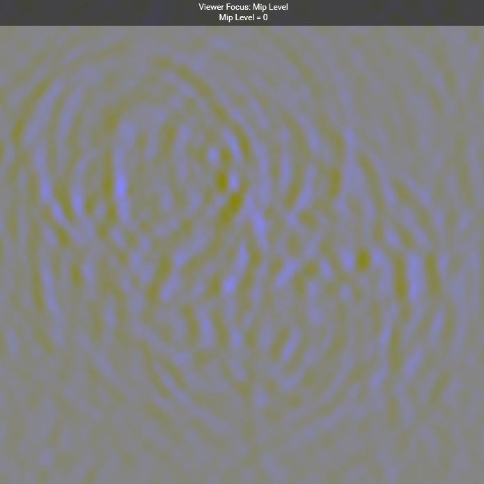
Height Map: R(Height), G(Velocity),BA(Normal.xz)
If we were to render Caustics using ray tracing, the light would scatter quite a bit when passing through the water surface, so sampling and denoising would be required.
As mentioned earlier, the main goal of this scene is to get familiar with the Vulkan Ray-Tracing API, so we didn’t use ray tracing for the Caustics rendering. Instead, we implemented it through the graphics pipeline, using a Height Map to generate a Caustics Map.
In detail, the algorithm calculates how much the incident light changes when it hits the water surface and bottom, based on the height difference between the two, and uses the Height Map to compute this variation. This change is represented by the difference between neighboring pixels and is used as a heuristic to describe the Caustics intensity.
Since human eyes are less sensitive to refraction and Caustics effects, this algorithm, while not physically perfect, is good enough to create a Caustics effect that aligns with the water surface, providing a fairly natural visual result for the audience.
// Calculate caustics map
// Vert
vec4 info = texture(waterHeightMap, inPos.xy * 0.5 + 0.5);
info.ba *= 0.1; // rescale normal

vec3 normal = vec3(info.b, sqrt(1.0 - dot(info.ba, info.ba)), info.a);
/* project the vertices along the refracted vertex ray */
vec3 refractedLight = refract(-light, originNormal, IOR_AIR / IOR_WATER);
vec3 ray = refract(-light, normal, IOR_AIR / IOR_WATER);

oldPos = project(inPos.xzy, refractedLight, refractedLight);
newPos = project(inPos.xzy + vec3(0.0, info.r, 0.0), ray, refractedLight);

gl_Position = vec4((newPos.xz + refractedLight.xz / refractedLight.y), 0.0, 1.0);


// Frag
layout(location = 0) in vec3 oldPos;
layout(location = 1) in vec3 newPos;
layout(location = 0) out float outFragColor;

void main()
{
    float oldArea = length(dFdx(oldPos)) * length(dFdy(oldPos));
    float newArea = length(dFdx(newPos)) * length(dFdy(newPos));
    outFragColor = (oldArea / newArea - 1.0) * 0.2;
}
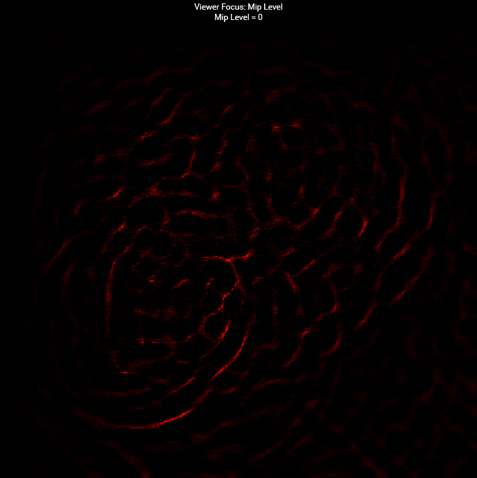
Caustics Map
Other features in Ray-Tracing Pipeline
A Callable Shader is a type of shader that supports indirect calls, allowing specific computations or operations to be invoked from other shaders in the pipeline, such as the ray generation shader or the hit shader. This mechanism provides greater flexibility by encapsulating certain calculations in separate shaders, thus optimizing the code structure. The Khronos Vulkan Samples provide use cases demonstrating how to leverage this feature.
Position Fetch is an optimization mechanism designed to simplify the process of retrieving intersection points in ray tracing. It allows shaders to directly access the intersection point’s position when a ray intersects an object, improving performance and enhancing code maintainability. This feature requires hardware support and depends on the VK_KHR_ray_tracing_position_fetch extension.
Vulkan synchronization: Fence, Femaphore and Pipeline-barriers
1. Fence: Used for synchronization between CPU and GPU.
- The CPU can wait for or query the completion of GPU work using functions like
vkWaitForFencesorvkGetFenceStatus. - A Fence is global, meaning the same Fence can be used for synchronization across different Command Buffers.
2. Semaphore: Used for synchronization between queues.
- A typical scenario is the producer-consumer relationship between different queues. For example, one queue can process an image, and once it’s done, another queue can read it.
- Semaphores are internal to the GPU and cannot be queried across frames or on the CPU.
3. Pipeline Barrier: Used for synchronization between different stages (like draw calls, dispatch, or traceRay) within the same queue, ensuring the correct order of resource access.
- A Pipeline Barrier is an explicit synchronization mechanism, commonly used to solve the following issues:
- Memory dependencies: Ensuring that writes from a previous operation are completed before being read by a subsequent operation.
- Stage dependencies: Ensuring that one stage completes before the next one begins.
- Resource layout transitions: For example, transitioning an image from
VK_IMAGE_LAYOUT_COLOR_ATTACHMENT_OPTIMALtoVK_IMAGE_LAYOUT_SHADER_READ_ONLY_OPTIMAL.
void buildComputeCommandBuffer()
{
	VkCommandBufferBeginInfo cmdBufInfo = vks::initializers::commandBufferBeginInfo();

	VK_CHECK_RESULT(vkBeginCommandBuffer(compute.commandBuffer, &cmdBufInfo));

	VkImageMemoryBarrier imageMemoryBarrier = {};
	imageMemoryBarrier.sType = VK_STRUCTURE_TYPE_IMAGE_MEMORY_BARRIER;
	imageMemoryBarrier.oldLayout = VK_IMAGE_LAYOUT_GENERAL;
	imageMemoryBarrier.newLayout = VK_IMAGE_LAYOUT_GENERAL;
	imageMemoryBarrier.image = storageImage.image;
	imageMemoryBarrier.subresourceRange = { VK_IMAGE_ASPECT_COLOR_BIT, 0, 1, 0, 1 };
	if (vulkanDevice->queueFamilyIndices.graphics != vulkanDevice->queueFamilyIndices.compute)
	{
		// Acquire barrier for compute queue
		imageMemoryBarrier.srcAccessMask = 0;
		imageMemoryBarrier.dstAccessMask = VK_ACCESS_SHADER_WRITE_BIT;
		imageMemoryBarrier.srcQueueFamilyIndex = vulkanDevice->queueFamilyIndices.graphics;
		imageMemoryBarrier.dstQueueFamilyIndex = vulkanDevice->queueFamilyIndices.compute;
		vkCmdPipelineBarrier(
			compute.commandBuffer,
			VK_PIPELINE_STAGE_TOP_OF_PIPE_BIT,
			VK_PIPELINE_STAGE_COMPUTE_SHADER_BIT,
			VK_FLAGS_NONE,
			0, nullptr,
			0, nullptr,
			1, &imageMemoryBarrier);
	}

	// prepare barrier
	VkImageMemoryBarrier imageBarrier = {};
	imageBarrier.sType = VK_STRUCTURE_TYPE_IMAGE_MEMORY_BARRIER;
	imageBarrier.srcAccessMask = VK_ACCESS_SHADER_WRITE_BIT;
	imageBarrier.dstAccessMask = VK_ACCESS_SHADER_READ_BIT;
	imageBarrier.oldLayout = VK_IMAGE_LAYOUT_GENERAL;
	imageBarrier.newLayout = VK_IMAGE_LAYOUT_GENERAL;
	imageBarrier.srcQueueFamilyIndex = VK_QUEUE_FAMILY_IGNORED;
	imageBarrier.dstQueueFamilyIndex = VK_QUEUE_FAMILY_IGNORED;
	imageBarrier.image = waterHeightMap.image;
	imageBarrier.subresourceRange = { VK_IMAGE_ASPECT_COLOR_BIT, 0, 1, 0, 1 };

	// Drop pass
	// -------------------------------------------------------------------------------------------------------
	vkCmdBindPipeline(compute.commandBuffer, VK_PIPELINE_BIND_POINT_COMPUTE, compute.pipelineDrop);
	vkCmdBindDescriptorSets(compute.commandBuffer, VK_PIPELINE_BIND_POINT_COMPUTE, compute.pipelineLayout, 0, 1, &compute.descriptorSet, 0, 0);
	vkCmdDispatch(compute.commandBuffer, waterHeightMap.width / 16u, waterHeightMap.height / 16u, 1);

	vkCmdPipelineBarrier(
		compute.commandBuffer,
		VK_PIPELINE_STAGE_COMPUTE_SHADER_BIT,
		VK_PIPELINE_STAGE_COMPUTE_SHADER_BIT,
		0,
		0, nullptr,
		0, nullptr,
		1, &imageBarrier);

	// Update height pass
	// -------------------------------------------------------------------------------------------------------
	vkCmdBindPipeline(compute.commandBuffer, VK_PIPELINE_BIND_POINT_COMPUTE, compute.pipelineUpdateHeight);
	for (uint8_t ii = 0; ii < updateHeightTimes; ++ii)
	{
		vkCmdDispatch(compute.commandBuffer, waterHeightMap.width / 16u, waterHeightMap.height / 16u, 1);
		vkCmdPipelineBarrier(
			compute.commandBuffer,
			VK_PIPELINE_STAGE_COMPUTE_SHADER_BIT,
			VK_PIPELINE_STAGE_COMPUTE_SHADER_BIT,
			0,
			0, nullptr,
			0, nullptr,
			1, &imageBarrier);
	}

	// Update normal pass
	// -------------------------------------------------------------------------------------------------------
	vkCmdBindPipeline(compute.commandBuffer, VK_PIPELINE_BIND_POINT_COMPUTE, compute.pipelineUpdateNormal);
	vkCmdDispatch(compute.commandBuffer, waterHeightMap.width / 16u, waterHeightMap.height / 16u, 1);

	if (vulkanDevice->queueFamilyIndices.graphics != vulkanDevice->queueFamilyIndices.compute)
	{
		// Release barrier from compute queue
		imageMemoryBarrier.srcAccessMask = VK_ACCESS_SHADER_WRITE_BIT;
		imageMemoryBarrier.dstAccessMask = 0;
		imageMemoryBarrier.srcQueueFamilyIndex = vulkanDevice->queueFamilyIndices.compute;
		imageMemoryBarrier.dstQueueFamilyIndex = vulkanDevice->queueFamilyIndices.graphics;
		vkCmdPipelineBarrier(
			compute.commandBuffer,
			VK_PIPELINE_STAGE_COMPUTE_SHADER_BIT,
			VK_PIPELINE_STAGE_BOTTOM_OF_PIPE_BIT,
			VK_FLAGS_NONE,
			0, nullptr,
			0, nullptr,
			1, &imageMemoryBarrier);
	}

	vkEndCommandBuffer(compute.commandBuffer);
}
The link provides some best practices for using Pipeline Barriers in Vulkan.
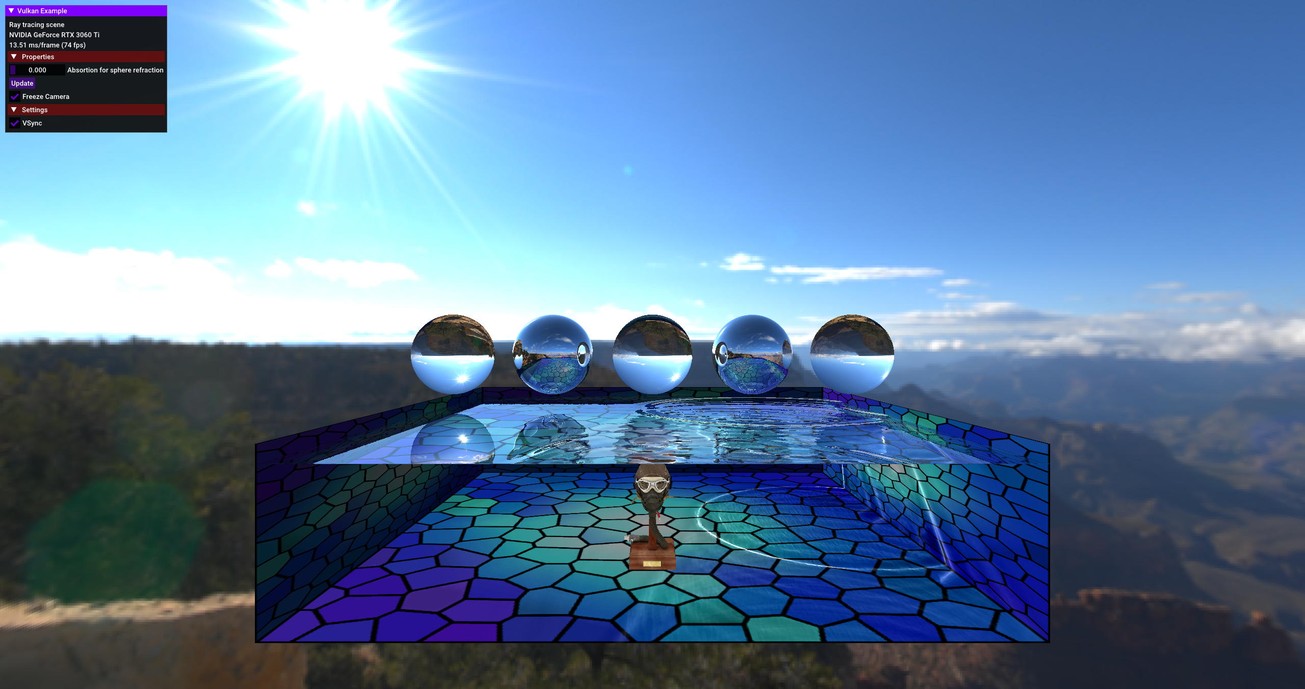
Final Scene
Miscellaneous
In addition to mirror reflections, diffuse reflections and other cases where outgoing light is scattered are also very common and challenging in ray tracing. In current mainstream real-time ray tracing renderers (specifically, path tracing renderers), efficient sampling algorithms and denoising techniques have always been key components (such as Nvidia’s Falcor). I’ve also been learning in this field, and in the future, I may work on some small projects specifically to further explore and practice this technology.
References
- https://raytracing.github.io/books/RayTracingInOneWeekend.html
- https://zhuanlan.zhihu.com/p/146144853
- Vulkan Samples: https://github.com/KhronosGroup/Vulkan-Samples
- WebGL Water: https://madebyevan.com/webgl-water/
- https://github.com/NVIDIAGameWorks/Falcor
- https://iquilezles.org/articles/spherefunctions/
The content of this blog post is original to the author. Please indicate the source and include the original link when reproducing it. Thank you for your support and understanding.